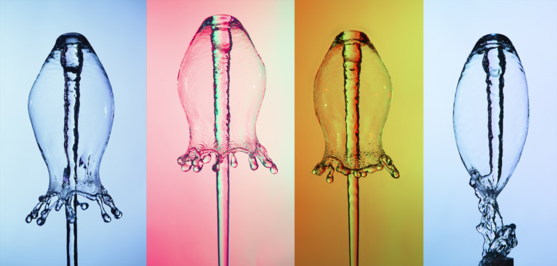
Each year I update experiments in the collection of the High-Speed photography lab at Rochester Institute of Technology (RIT). One of this year’s additions is an air-powered water bell.
In this experiment, air pressure is used to push a column of water vertically. The top of this column of water falls back on itself as the bottom of the column is still rising. This creates two masses of water that collide in the air. The resulting bell is created by the falling column of water being forced into a bell shape by the opposing column of water.
Recently, this type of system has come to my attention by its use in several advertisements. The build for this device is very simple and inexpensive assuming that you have access to a small shop air compressor.
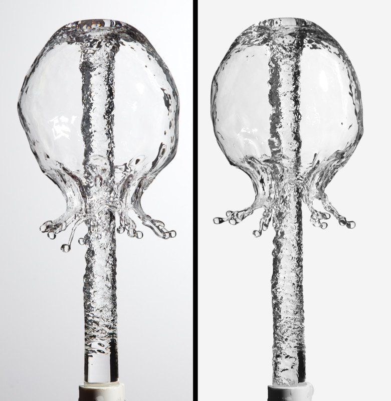
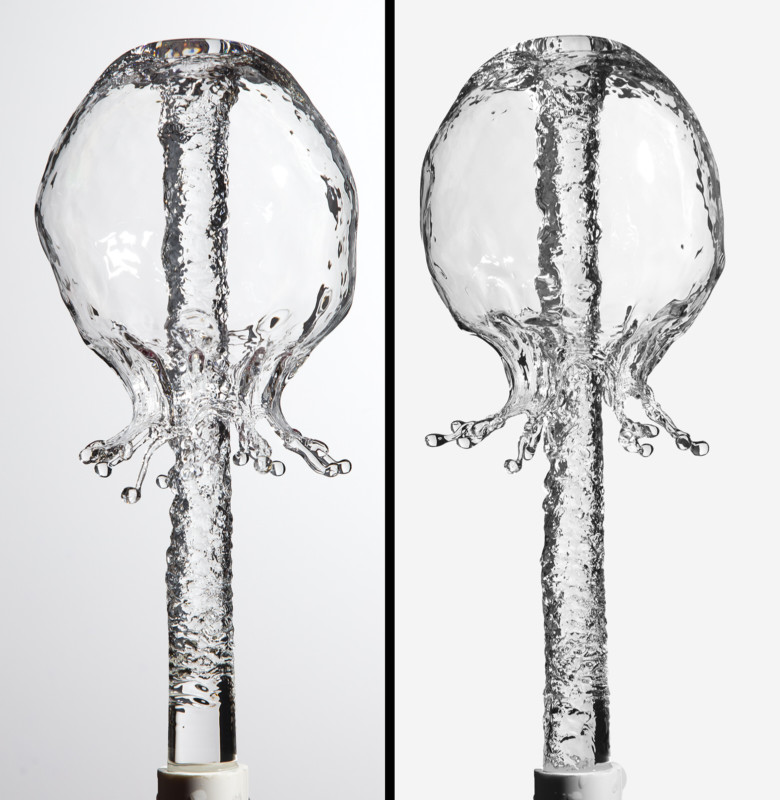

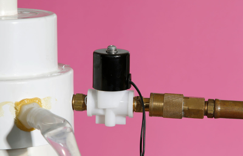
The air compressor has a built-in regulator that is set to 35 psi and I use a 12V DC Normally Closed air valve. Since the air valve has to be precisely controlled, I use an Arduino to make a voltage pulse to open the valve. In the image above, the air valve was open for 65 milliseconds.
There are a number of ways to control the flash, and here I used a simple reed switch to control a Profoto B1X 500 flash set to one of the fastest settings. The flash can be triggered from the Arduino or an IR trigger can be used that sets off the flash when the water bell has risen to the desired height. Working with the students I often use the IR trigger since it is good experience. The water bell is very repeatable if the water is filled to the same location for each trial.
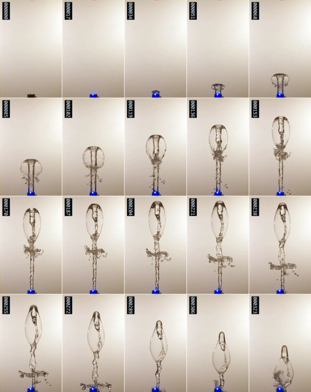
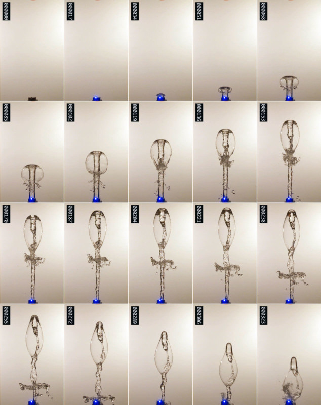

Above is a typical sequence of shapes from the water bell system. Imaged with a Chronos camera running at 1057 frames per second (www.krontech.ca). The blue LED light at the bottom of each frame is an indicator that turns on when the air valve is opened. The start of the blue light is a reference for timing with the microprocessor. Between each of the images above is 16 ms. This full sequence covers .305 seconds. The largest the water bell forms in this sequence is about 12 cm in diameter. In this sequence, the air valve was open for 75 ms. and the compressor was set to 35 PSI.
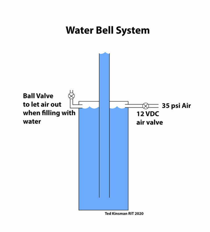
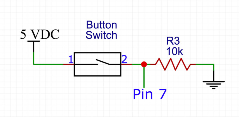

Here the PVC piping is shown in cross-section. The air valve on the left is an air solenoid valve controlled by 12 VDC. The voltage for the switch is controlled by a simple reed switch controlled by an Arduino microprocessor. The reed switch supplies electrical isolation between the 12VDC supply and the Arduino. The reed switch also actuates in 60 microseconds so it does not affect the characteristics of the system. The ball valve on the left allows the air to leave the large cylinder when water is topped off in the central smaller cylinder.
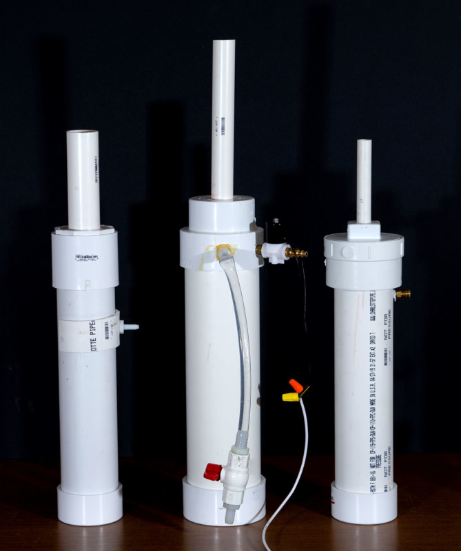
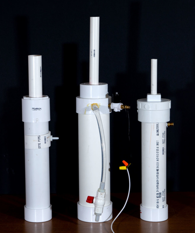

Various water bell tubes. The center tube was used for the images in this paper and measures 29 inches high. The large pipe is 4 inches in diameter and is 17 inches high. The center tube is 1-inch diameter PVC and starts 1.5 inches above the bottom and extends to 29 inches above the table. The center system has an extra cap glued to the top for stability. There are numerous ways of combining PVC fittings to making these systems.


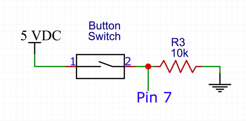

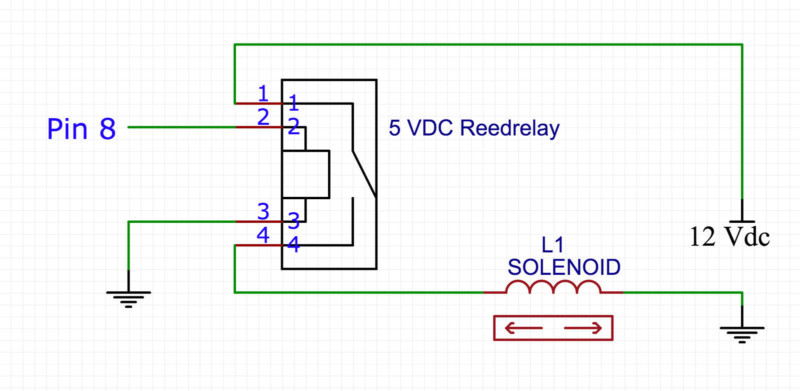
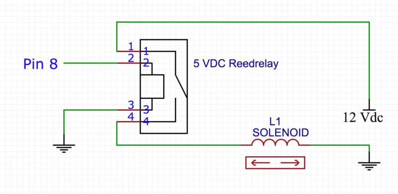

Sample Arduino code:
/*
* Water-Bell2020
* Ted Kinsman [email protected]
* Assistant Professor of Photographic Sciences
* at Rochester Institute of Technology (RIT)
* Nov 6, 2020
* this program sends a pulse to an air valve
* from a push button.
* This system will trigger a flash a bit after the pulse
*/
const int flashPin = 3; // Set flash to pin 3 controls the opto-isolator
const int LED = 4;
const int StartButton = 7; // Set push button to pin 7 this will be an input from a switch
const int Valve = 8; // Set valve to pin 8 connects to a reed switch which
// controls the solenoid valve
int buttonState = LOW; //value read from push button
int ValvePause = 65; // set delay to let solenoid open door (milliseconds)
int flashDelay = 215; // Set a delay for flash to be triggered: adjust
// this for part of collision you want to photograph
void setup() {
pinMode(flashPin, OUTPUT); // Set flash pin (pin 3) as an output
pinMode(LED, OUTPUT); // LED light is an output
pinMode(StartButton, INPUT); // Set pin 7 as an input
pinMode(Valve, OUTPUT); // Set pin 8 as an output
}
void loop() {
buttonState = digitalRead(StartButton); // reads value of button
if (buttonState==HIGH) { //starts the sequence to open the valve if the button is pressed
digitalWrite(LED, HIGH); // turn on LED to show air valve has been opened
digitalWrite(Valve, HIGH); // makes the air valve (12 VDC solenoid) open
//note: the control here uses a reed switch
delay(ValvePause); //keeps solenoid open for time (milliseconds)
digitalWrite(Valve, LOW); // turns off the solenoid
delay(flashDelay); //wait the flash delay time to trigger flash
digitalWrite(flashPin, HIGH); //trigger the flash
delay(1); //keep flash trigger pin high long enough to trigger flash
digitalWrite(flashPin, LOW); //turn off flash trigger
delay(5000); // keeps the system in a pause mode to avoid false triggers
digitalWrite(LED, LOW); //turns off the LED
// Note: when the LED is off the system is ready to fire
} else{ // if there is no trigger, pins are kept low (off)
digitalWrite(flashPin, LOW); //sets pins low
digitalWrite(Valve, LOW); //sets pins low
}
}
References: A Simple to Build Double Water Drip System For High Speed Photography
About the author: Ted Kinsman is the 2019 recipient of the Schmidt Laureate or outstanding contributions to the progress of biocommunications. Kinsman has worked as an optical engineer, a physicist, and a physics instructor before joining the Photographic Sciences Dept. at RIT. His work has appeared on The Discovery Channel, Crime Scene Investigations (CSI), The X-Files, South Park, The Tyra Banks Show, and The Frozen Planet series. Kinsman is currently an Associate Professor in the school of Photographic Arts and Sciences (SPAS) where he teaches Photographic Instrumentation, Scanning Electron Microscopy, and High-Speed Imaging. His most recent book is Cannabis: Marijuana under the microscope.