Originally, the geometric chuck was a device to make ornate patterns on a lathe. Invented in the 1860s, the device could have up to 8 layers—each driven by a central shaft.
There are several of these complex devices still in existence and on display in museums. Each layer can have a unique set of gears to control the rotational rate of the layer in response to the central shaft and be displaced a radial distance from the central shaft.
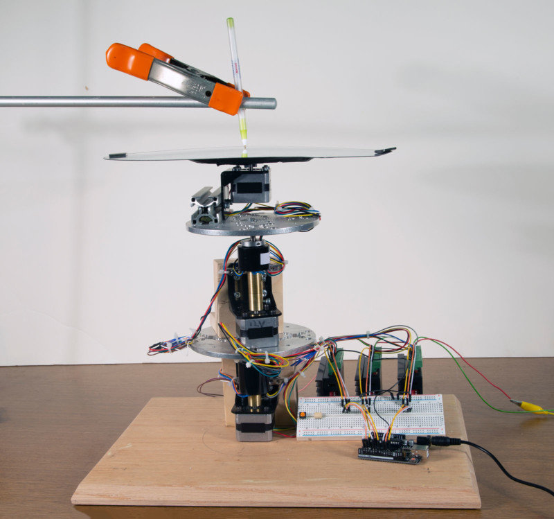
Evaluating the design, I decided to update the system and use a programable stepping motor for each layer. I limited this drawing machine to three layers because of the cost of employing slip-ring electrical connectors, which allow electricity to flow to rotating objects without twisting wires.
I should note that the stepping motors open up a number of possibilities from gear designs. Mainly the rotation rate of each layer can be quickly adjusted. The stepping motors are controlled by a stepping motor controller which in turn is programmed by an Arduino microprocessor.
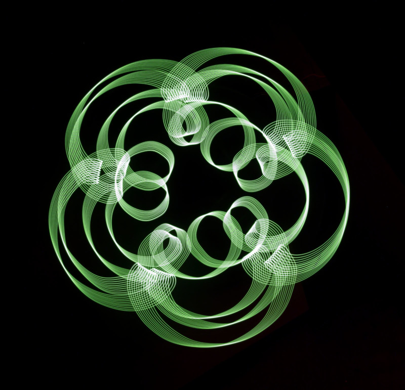
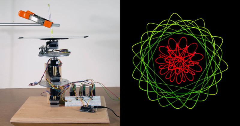
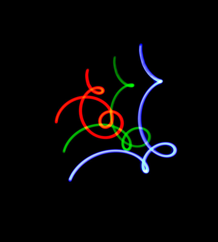
After experimenting with the setup for a while, the need for a simulator to help predict patterns became obvious. Since I often teach using Excel, it seemed to be the logical choice to use. The pattern created by a point on the top platter is easy to calculate. Here this pattern is recorded by placing a small LED light on the top platter and photographing the motion in a dark room.
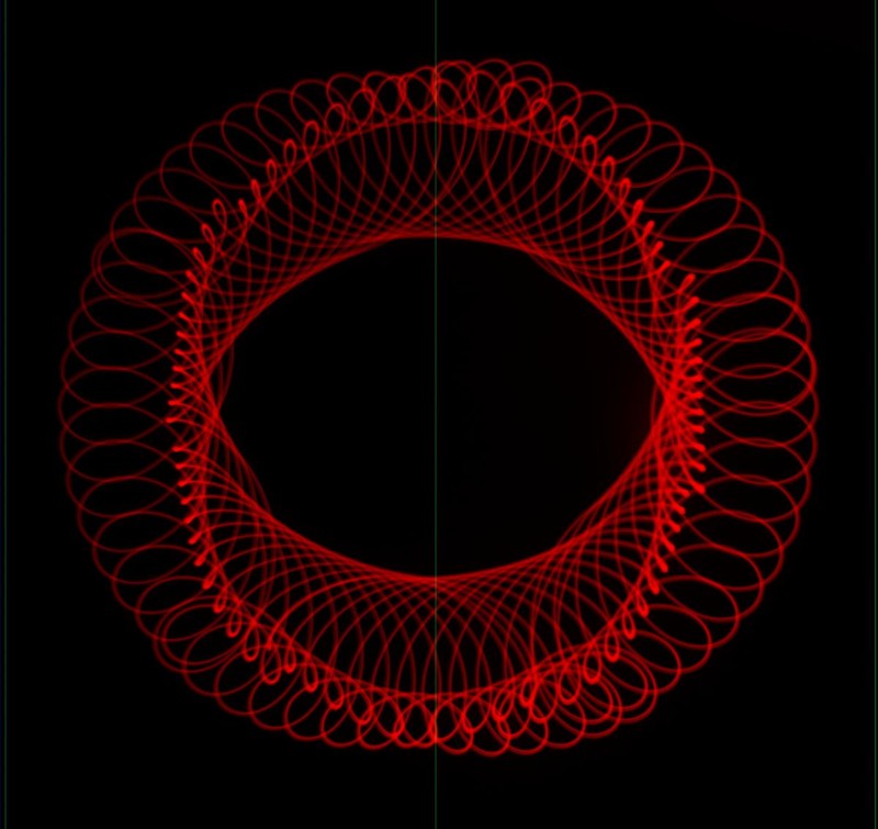
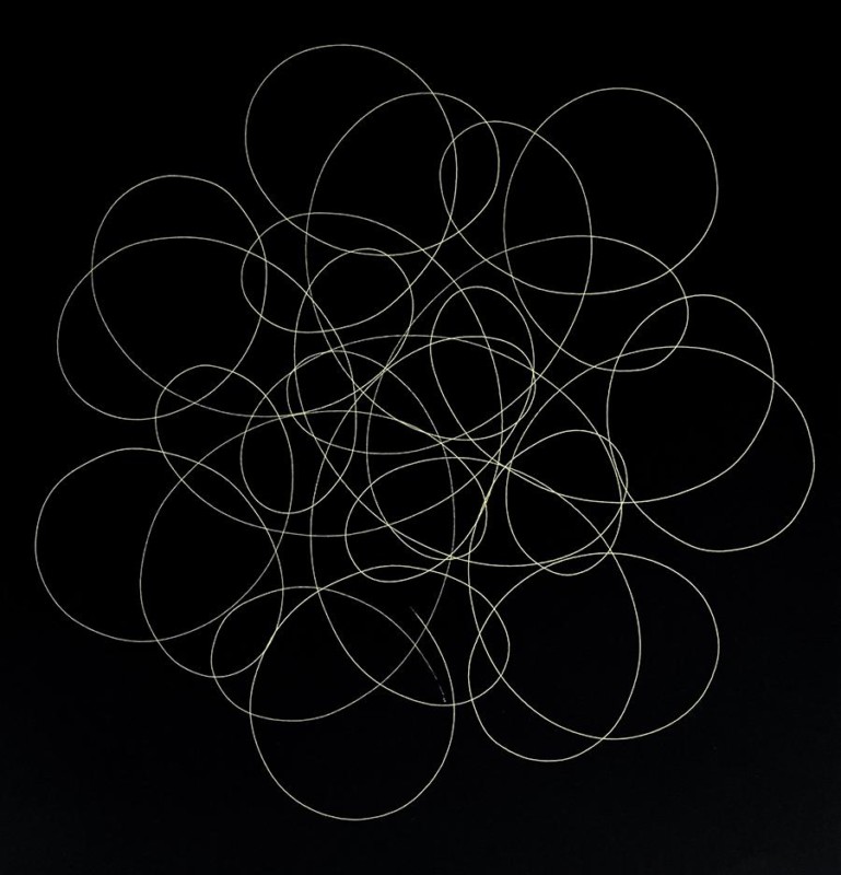
When paper is placed on the top platter and a pen fixed to a stand (the Earth frame of reference) is used – we record a different pattern.
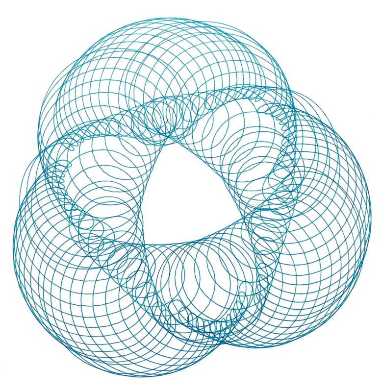
This difference is similar to looking at the orbit of Mars from Earth versus looking at the orbit of Mars from a stationary point outside our solar system. Calculating the patterns that the pen makes on the paper is a good exercise in relative coordinate systems.
This is one of the surprising characteristics of the device: an LED placed on the top platter will trace out one pattern, while a pen on a stand on the floor will trace out another curve on a sheet of paper placed on the top stage. The two patterns created by changing the coordinate systems only serve to intrigue the viewer.
In this system, each of the platters can be displaced from the central bottom stepping motor that acts as a reference. Each stage can be driven clockwise or counterclockwise at any speed. The pen can be placed anywhere on the top platter. Each location will yield a different pattern, as will the angular position of the plates when the device is started. These variables all add up to make a wonderfully simple device with a vast selection of possible patterns.


The Arduino and stepping motor controllers drive the motors. The stepping motors are mostly designed to move an object from one location to a second position with positional accuracy. This modern geometrical chuck requires rotational accuracy. The current drivers work in integer steps, and I suspect the driver circuits are not as accurate as they could be.
Here’s the sample code:
/*
wheels-3-Final-program.ino
This is sample code for wheels on wheels on wheels project
This project simulates a geometrical chuck from the 1860s with modern
stepping motors and an Arduino microprocessor.
There are three steppers used in this project all on top of each other.
Conductive slip rings are used to carry electricity to the motors on rotating
platforms.
stepper1 is base
stepper2 is 2nd level
stepper3 is third level (top)
November 1, 2020
Ted Kinsman [email protected]
Example sketch to control a stepper motor with TB6660 stepper motor driver,
AccelStepper library and Arduino: acceleration and deceleration.
*/
#include
// Define stepper motor connections and motor interface type. Motor interface type must be //set to 1 when using a driver:
#define dirPin1 3 //stepper 1 (bottom stepper) direction control on pin 3
#define dirPin2 7 //stepper 2 (middle stepper motor) direction control on pin 7
#define dirPin3 11 //stepper 3 (top stepper) direction control on pin 11
#define stepPin1 2 //stepper 1
#define stepPin2 6 //stepper 2
#define stepPin3 10 //stepper 3 (top stepper)
const int enPin = 4;
// Create a new instance of the AccelStepper class:
AccelStepper stepper1 = AccelStepper(AccelStepper::DRIVER, stepPin1, dirPin1);
AccelStepper stepper2 = AccelStepper( AccelStepper::DRIVER, stepPin2, dirPin2);
AccelStepper stepper3 = AccelStepper( AccelStepper::DRIVER, stepPin3, dirPin3);
void setup()
{ //these steppers move 200 steps for 1 revolution
stepper1.setMaxSpeed(200); //steps per second units for rotation
stepper2.setMaxSpeed(200); // steps per second units for rotation
stepper3.setMaxSpeed(200); // steps per second units for rotation
// define speeds and directions
stepper1.setSpeed( -35); // bottom motor set to -35 steps per second (counter clockwise)
stepper2.setSpeed(100); //middle motor set to 100 sets per second (clockwise)
stepper3.setSpeed( -115); // top motor set to -115 steps per second. (counter clockwise)
}
void loop()
{
// run all motors at constant speed
stepper1.runSpeed();
stepper2.runSpeed();
stepper3.runSpeed();
}
I hope you enjoy this project. Creating designs is quite mesmerizing with this device and a wonderful way to teach a little mathematics.
References: “The Mechanical Drawing of Cycloids, The Geometric Chuck”
About the author: Ted Kinsman is the 2019 recipient of the Schmidt Laureate or outstanding contributions to the progress of biocommunications. Kinsman has worked as an optical engineer, a physicist, and a physics instructor before joining the Photographic Sciences Dept. at RIT. His work has appeared on The Discovery Channel, Crime Scene Investigations (CSI), The X-Files, South Park, The Tyra Banks Show, and The Frozen Planet series. Kinsman is currently an Associate Professor in the school of Photographic Arts and Sciences (SPAS) where he teaches Photographic Instrumentation, Scanning Electron Microscopy, and High-Speed Imaging. His most recent book is Cannabis: Marijuana under the microscope.